

Solar Mounting Systems: What Every EPC Contractor Needs to Know
Solar mounting systems are the unsung infrastructure of every photovoltaic installation. They hold panels at the correct angle, resist wind and environmental loading for 25 or more years, and must do all of this with minimal maintenance. For EPC contractors, selecting the right mounting system is as critical as selecting the right panel.
Why Mounting System Selection Matters
A solar panel’s output is only as reliable as the structure holding it. Mounting system failures, including corrosion, fatigue cracking, fastener loosening, and thermal distortion, are not just maintenance problems. They are insurance claims, warranty disputes, and in some cases complete array rebuilds. The economics of a solar farm depend on 25 years of uninterrupted structural performance.
Roof Mounting vs Ground Mounting: Key Differences
|
Factor
|
Roof Mounting
|
Ground Mounting
|
|---|---|---|
|
Structural load path
|
Transferred to roof structure
|
Transferred to driven piles or ballast
|
|
Tilt adjustment
|
Fixed to roof pitch
|
Adjustable 10-45 degrees typically
|
|
Wind loading
|
Uplift critical
|
Both uplift and lateral
|
|
Maintenance access
|
Restricted
|
Open access
|
|
Primary aluminium component
|
Rail, clamp, roof hook
|
Rail, clamp, frame, bracket
|
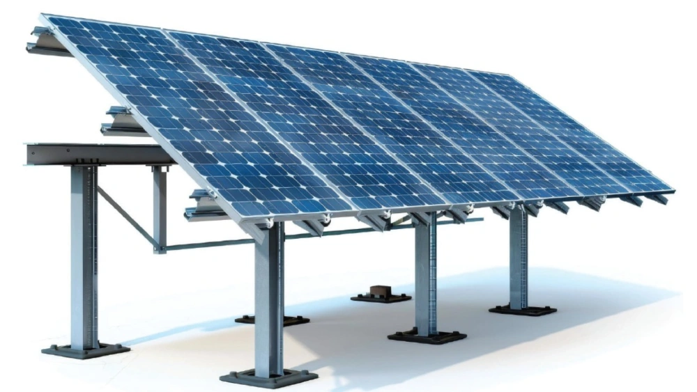
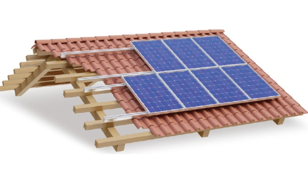
Aluminium Mounting Rails: The Core Structural Component
The mounting rail is the primary structural element in both roof and ground systems. Key rail selection criteria for EPC contractors include:
- Alloy specification: 6063-T5 or T6 for balance of strength, extrudability, and corrosion resistance
- Section geometry: I-beam or hat-section profile for structural efficiency
- Anodizing specification: Minimum Class 20 for standard environments; Class 25 for coastal zones
- Length and splice compatibility: Rail length affects installation efficiency; splice bars must maintain structural continuity
- Slot geometry: T-bolt slots must be compatible with mid and end clamp specifications
Mid Clamps vs End Clamps: A Technical Comparison
|
Feature
|
Mid Clamp
|
End Clamp
|
|---|---|---|
|
Position
|
Between two adjacent panels
|
At the edge of the array row
|
|
Function
|
Secures two panels simultaneously
|
Secures single edge panel
|
|
Load path
|
Symmetrical compression
|
Asymmetrical, edge retention
|
|
Panel thickness range
|
Adjustable (typically 30-50mm)
|
Adjustable (typically 30-50mm)
|
|
Quantity per row
|
(Panels per row minus 1) x 2
|
4 per row end
|
Corrosion Specification for Challenging Environments
One of the most frequent errors in solar procurement is specifying standard anodized aluminium for coastal environments. Salt aerosol penetrates standard Class 15 or Class 20 anodic layers over time, causing surface pitting that compromises structural integrity.
Environment-Specific Specification Guidelines
- Standard inland: Anodized Class 20 (20 micron minimum anodic layer)
- Coastal within 5km of sea: Anodized Class 25 (Qualanod seaside specification)
- Marine and offshore: Class 25 plus appropriate stainless fasteners throughout
- Desert and high-UV: Powder-coated with UV-stable polyester, Qualicoat certified
- Industrial pollution zones: Anodized Class 25 or powder-coated Qualicoat Class C4/C5
Installation Efficiency: The Hidden Cost Driver
Labour accounts for 30-40% of solar installation cost. Mounting system design significantly affects installation speed. Alumex’s mounting system components are designed for rapid field assembly. Rail splice bars engage without tools; mid and end clamps adjust to panel thickness without pre-measurement. On a 1MW rooftop project, these incremental efficiencies can reduce installation time by 15-20%.
Procurement Checklist for EPC Contractors
- Confirm alloy specification (6063-T5/T6) and request mill test certificates
- Verify anodizing standard against project environmental classification
- Check clamp-to-panel compatibility with confirmed panel thickness from supplier
- Request structural section properties for engineering verification
- Confirm fastener material for environmental suitability
- Verify lead time and minimum order quantities before contract award


